How to use the gps tracking device configuration software
How to use the gps tracking device configuration software
1.Compatibility
This article is compatible with the following Totemtek products:
● AT07 2G/3G/4G
● AT09 2G/3G (exclude TPMS version)
2. Things before start
Before you start to connect the device with PC/Laptop, make sure you have below things ready.
2.1 Hardware/Software
● PC or laptop (windows based)
● Device with enough battery (check if the LED is blinking when you power on the device).
● Regulated DC power supply DC 12V/24V (in case device is in low battery).
● USB cable (Purely USB cable): USB cable for android mobile with mini USB interface.
● .Net framework 4 or above.
The configurator Manager requires .Net framework component. If you are not sure, you can check control panel
Apps list in your Windows.
2.2. Configurator Manager folder
The content of the folder can refer as below:

GPRSlog: This folder will create automatically once the configurator manager has been set up as a TCP listener to
receive data from device.
USBLog: this folder will create automatically once the configurator is running. Device running log will keep under this
folder. Client can send the TXT log under this folder to our support team to diagnose the problems.
STD configurator Manager.exe: this is configurator of the device (windows based application).
UsbLibrary.dll: this is library of USB. It should be always kept in the same folder.
3. Interface Introduction: start up
This is the initial interface once Configurator Manager is running, if you got any error, please check as below:
● Make sure the .net framework 4 or above has been installed.
● Make sure the UsbLibrary.dll and configurator manager are in the same folder.
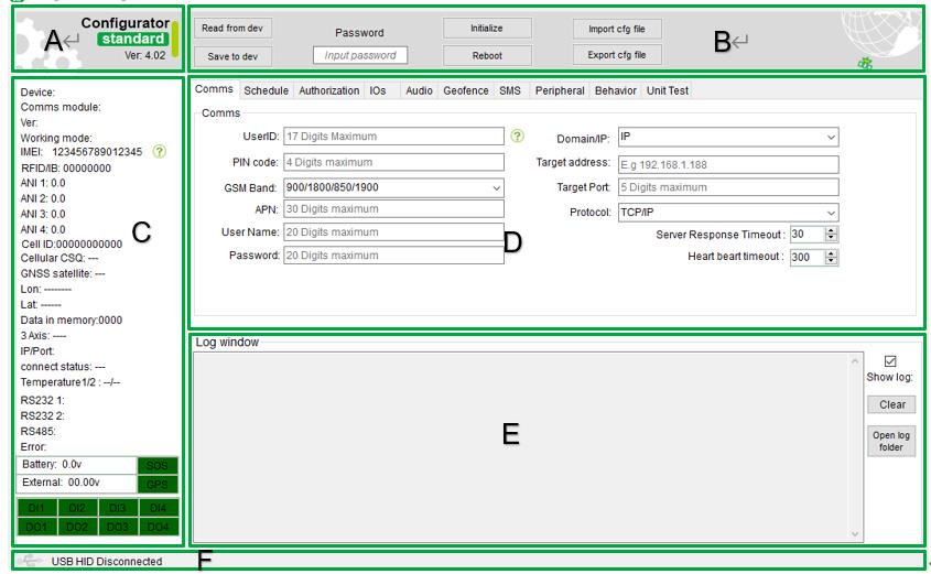
Section A:
This section is the window to display the configurator version (standard/beacon/COM/TP) and version number (4.02).
Section B:
This section has provided some basic operation buttons and password input window to avoid access without authorization.
Section C:
This is the device status window. It contains connectivity status, device IO status, power status, device IMEI, firmware
version and module number.
Section D:
This is the most important window; it contains several sub tab in this section. All the desired parameter can be changed
in this section.
Section E:
This section a log display window. The device will save the log continuously into a txt file and also display in the log
window.
Section F:
This is USB connection indicator, the communication between device and PC/laptop relies on the USB connection. So please
make sure the connection has been established.
3.1 Section A: Configurator version

Totemtek product comes with several version of the configurator manager, each one is combining with different product, please follow below match pair.
● STD/Standard: AT07 2/ 3/4G, AT09 2G/3G/4G.
● Beacon: AT08, AT20(Solar power unit)
● TPMS: AT09 TPMS
● COM: AT04, AT05
● TP: TP08, TP09
Ver:4.02: This is the configurator version.
3.2 Section B: Basic operation button

● Read from dev: read the setting from device.
● Save to dev: save the setting into device
● Password: entry the password before any operation.
● Initialize: reset to factory setting.
● Reboot: reboot device.
● Import cfg file: import the device parameter from a XML file.
● Export cfg file: export current setting into a XML file.
3.3 Section C: Device status
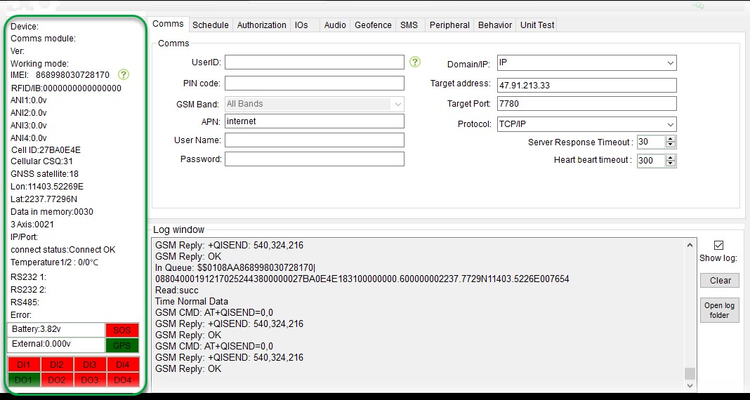
● Device: AT07 (device name, AT07, AT09 etc.)
● Comms module: GSM/3G/4G module name
● Ver: 1.08 (device firmware version)
● Working mode: device working mode sleep/deep sleep
● IMEI: GSM module IMEI number
● RFID/IB: RFID ID number of IButton number
● ANI 1 - ANI4: the voltage or percentage from analog input
● Cell ID: cell tower ID
● Cellular CSQ: GSM signal strength (Maximum 31)
● GNSS satellite: (number of GPS/GPS/BEIDOU fixed)
● Lon: longitude
● Lat: latitude
● Data in memory: 3 Axis: (3 axis vibration strength)
● IP/Port: (current target server and port)
● Connect status: (initialize/fail/off)
● Temperature: temperature value from 1 wire interface
● RS232: specific protocol in using on this port
● RS232: specific protocol in using on this port
● RS485: specific protocol in using on this port
● Error: reserved
● Battery: the internal battery voltage
● External : external power supply voltage
● DO1~DO4: digital output status of the device (red color is deactivated; green color is activated)
● DI1 ~ DI4: digital input status of the device (red color is deactivated; green color is activated)
● SOS: SOS button (red color is deactivated; green color is activated)
● GPS: GPS antenna status (red color is disconnected; green color is connected)
3.4 Section D: Parameter tab
This is main section where the device settings are changed.
3.4.1 Section D_sub: Comms

● UserID: this ID will replace the IMEI in the GPRS string if it has been set. Normally leave it in blank.
● PIN code: some SIM needs a pin code/password to work normally.
● APN/User Name/Password: APN user name and password.
● Domain/IP: target is domain or IP.
● Target address: domain address or IP address.
● Protocol: TCP/IP, UDP/IP.
● Server Response Timeout: TCP/IP, ACK response time, if no response within the pre-set time, device will send same data again.
● Heart beat time out: Heart beat package (BB) time interval.
3.4.2 Section D_sub: Schedule

● Sending data by movement or ignition ON/OFF ①
Combined with ignition: by Movement/By ignition
● is the trigger for ②/③
Caution: ACC+ or DI1+ is the PIN for the ignition connection. If ACC+/DI1+ no connected, device will always use 'by movement'.
● Movement detection
Ignition sensor: on (device in movement status once ignition on).
3 Axis Accelerometer: On (use 3 Axis to detect the movement).
Movement detection delay to wake up: X secs (after X secs vibration, device wake up).
● Sending data by movement or ignition ON/OFF ②
Minimum time: X seconds; (send data in X second interval).
Minimum distance: meter; (send data in Y meter interval).
Minimum veer: degree (send data in Z degree interval).
Each time/distance/veer (X, Y, Z) thread are separately, set as '0' will disable one of them.
If ① has been selected as “by ignition” and ACC/DI1+ has connected, device will start to count when ignition on and X
second later will send out 1pcs time interval data, and after Y meter distance, send 1pcs distance data. And if veer
change Z degree, it will send out 1pcs veer data.
If ① has been select as “by movement”, device will start to count when vehicle moving and X second later will send out
1st data, and after Y meter distance, send 1pcs distance data. And if veer change Z degree, it will send out 1pcs veer
data.
● Ignition OFF or Stop ③
Minimum time: X seconds.
If ① has been selected as “by ignition” and ACC/DI1+ has connected, device will start to count once ignition off and X
second later will send out 1st data.
If ① has been select as “by movement”, device will start to count when vehicle stop and X second later will send out 1st
data.
● Sleep/stop Definitions
Working mode: Normal/Sleep/Deep Sleep
Normal: Cellular module and GPS module is normal working.
Sleep: Cellular module working, GPS module shut down.
Deep sleep: Cellular module and GPS module both shut down.
Sleep delay: X seconds
When device stop, device will go to working mode (sleep/deep sleep) if no vibration.
3.4.3 Section D_sub: Authorization

● Authorize ID: these are the IDs section for RFID or iButton.
Click 'detect iButton/RFID', it will turn to green. Once the iButton has been activated, the ID will fill in the ID list
automatically.
● Covert.
The ID print on the RFID is in ASCII code, the configurator required a Hex code. Put the ID on tag body (in the picture
is 0001880284) into the configurator, it will change to Hex and then save into device.
3.4.4 Section D_sub: IOs

● Digital input
IN1+/IN5: on/off; If 'OFF' was selected, this IO will not response for input high/low.
● Digital Output
User define: if you want to send SMS to control this output, should select this item.
Off: turn off digital output
RFID/iButton: control by firmware, will reject the command (016) and response 'format error' when you send SMS.
● Analog input
On/off: on off the analog input.
Percent: the GPRS string will change to percent instead of voltage itself. Minimum voltage 'L' and maximum voltage is
'H'. the unit is mv, not V. 5000 means 5V.
In this example, maximum level is 5V, and minimum is 0V. if the analog input reading is 2.5V, the GPRS string will send
0050(50%) in the string.
3.4.5 Section D_sub: Audios

● Authorized monitor phone
Auto answer: on/off
Phone 1/Phone2/Phone3: Phone number list that device will pick up. All the number out of this list will be rejected.
3.4.6 Section D_sub: Geofence

● Geo fence
Copy the coordinate from Section B directly for the coordinate.
3.4.7 Section D_sub: SMS

● SMS target phone number
ON/OFF: send a SMS alarm to preset mobile number if alarm has been triggered (some carrier required country code, take a test before installation)
TOW: when device is parking and ignition off, vehicle move out from a circle for 200m.
3.4.8 Section D_sub: Peripheral

● Temperature Alarms
On/off: on/off temperature interface (1 wire interface).
Low: low temperature to trigger the events.
High: high temperature to trigger the events.
● RS232:
RS232 1 protocol/RS232 2 protocol: binding specific protocol for the RS232 port.
● RS232:
RS485: binding specific protocol for the RS232 port.
3.4.9 Section D_sub: Behavior

● Speed Alarms:
Over Speed: on/off over speed alarm.
Max speed: pre-set value for over speed alarm.
● OBD:
OBD data time: the time interval of the OBD string to device.
Max Acceleration/Max Breaking: acceleration from OBD string.
3.4.10 Section D_sub: Unit test

● New Firmware
Press 'load' to find the firmware (.bin file).
And 'start' to flash device.
● TCP listener (OTA IP)
This is the target IP for the remote device not able to connect with USB, and flash firmware over the air.
● Command
In this section, you can send a command to device directly by USB. And it can also provide a complete GPRS command with
checksum. It can also could be a small tool to help you calculate the checksum for different string.
● Device list
Disconn: disconnect the connected device
All: select all connected device.
Load: load the device CFG file (parameter XML file).
Save Config: save the configurator to device over the air.
OTA: update firmware over the air.
● USB CMD list
Camera: take a picture
RFID: generate a stimulated RFID data.
Send: send a GPRS message.
Clear: clear the data in memory.
OUTA~OUTB: engage OUTA ~OUTB. (make sure the output working mode is in “user define”).
Send SMS: send a SMS (fill the phone number to in the blank) to a mobile phone to get the mobile number of device.
3.5 Section E: log window

● Show log:
Device will print the log or not.
● Clear:
Clear the log in the log window.
● Open log folder:
Device will write into a TXT automatically; the file name is current date. These logs are useful information for our support team if your device has problem.

3.6 Section F: USB connectivity

● USB HID Disconnected
USB icon will turn to green once the USB connection has been established.


4. Operation example
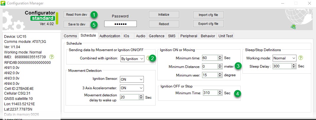
4.1 How to change APN/IP/Port to device?

1. Read from dev: read the setting from device first. Don't operate anything before you read from device.
2. APN: change the APN you want.
3. IP/Port: change the IP and port.
4. Save to dev: save the setting to device.
4.2 How to change the data time interval?
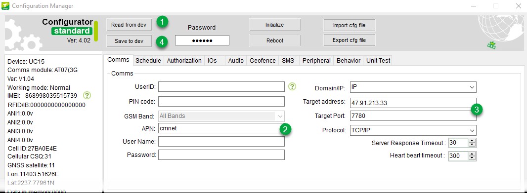
1. Read from dev: read the setting from device first. Don't operate anything before you read from device.
2. Sending data by Movement or ignition ON/OFF: select the desired trigger 'by movement' or 'by ignition'.
3. Ignition ON or moving: change the data time interval and minimum distance for data and minimum angle.
4. Ignition OFF or Stop: set the time interval when vehicle stop
5. Save to dev: save the setting to device.
In this example, if ignition on, device will send data 1 data in 60s interval, and send 1 data if angle changes 15
degree, no distance data ('0' in the example).
if ignition off, device will only send data in 310s interval.
4.3 How to export the device parameter to an external file?
1. Read from dev: read the setting from device first. Don't operate anything before you read from device.
2. Change the desired setting.
3. Export cfg file: export the parameter setting file into a XML file.
4.4 How to quick set parameter for bath devices?
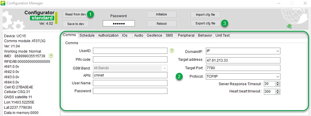
1. Import cfg file: load the setting from an external CFG file (XML file).
2. Change the desired setting.
4.5 How to flash the firmware for device?

1. Load: load the firmware.
2. Select the correct firmware from folder.
3. Start: start to flash the firmware.
4.6 How to get a correct GPRS command checksum?
1. Entry the command (full command list can found in our user manual).
2. Click 'GPRS CMD format'
3. The one in gray color “$$0024CF000000,016,B,16B” (6B is the checksum) string is complete command with checksum.
GPRS command format can be found in our communication protocol.
4.7 How to send a command to device in configurator?

1. Entry the command (full command list can found in our user manual).
2. Click 'USB' to send the command to device.
3. Configurator manager will pop up a successful window if the command is in correct format.
